
What is a magnetic flow meter?
A magnetic flow meter is an instrument that utilizes Faraday’s law of electromagnetic induction to measure the volumetric flow of a conductive liquid. When a liquid flows through a uniform magnetic field built into the meter, it cuts through the magnetic lines of force and induces a small voltage between the two electrodes. This voltage is proportional to the average flow rate of the fluid; multiplied by the cross-sectional area of the pipe to calculate the volume flow rate.
Characteristics of Magnetic Flow Meters
| Advantage | Description |
|---|---|
| No moving parts & near‑zero pressure loss | The flow tube is smooth and contains no throttling elements, so it introduces virtually no energy loss and requires minimal maintenance. |
| Wide fluid compatibility | Any liquid with conductivity ≥ about 5 µS/cm (model dependent) can be measured—clean water, wastewater, slurries, and corrosive solutions alike. |
| Broad turndown & good linearity | Turndown ratios of 150 : 1 or higher are achievable, and the output signal is almost perfectly linear with flow velocity. |
| Insensitive to density, temperature, and pressure | Because the measurement is based on induced voltage, results are practically independent of fluid properties, making the meter ideal for variable process conditions. |
Table of Characteristics of Magnetic Flow Meters
Limitations and Precautions
- Only conductive media can be measured: oil, pure RO water, insulating liquids and gases cannot be used.
- Installation requirements of full pipe, reliable grounding: empty pipe or air bubbles will cause zero drift; poor grounding is easy to introduce noise.
- Sensitive to strong magnetic field, vibration: need to avoid large motors, transformers and other environments, in high vibration occasions with bracket vibration damping.
Why Is It Vital That It Is Installed Correctly?
Magnetic flowmeter relies on electromagnetic induction to measure velocity – a full tube, stable flow field and reliable grounding are prerequisites for accurate readings. Improper installation not only results in drift, noise, and zero flow readings, but also shortens the life of the lining, electrodes, and electronics, and increases maintenance costs.

Pre-Installation
| Check Item | Key Point | Common Oversight |
|---|---|---|
| Fluid Conductivity | ≥ 5–20 µS/cm (model‑dependent threshold) | Using ultra‑pure RO water or insulating oils that fall below the minimum conductivity |
| Temperature / Pressure / Solids Content | Must be within the meter’s specified range | Ignoring liner wear limits when handling high‑temperature slurries |
| Documentation | Review P\&ID, layout drawings, and the manufacturer’s manual | Failing to verify straight‑run requirements |
| Tools & Consumables | Torque wrench, grounding rings, shielded cable, corrosion‑resistant gaskets | Substituting standard gaskets that corrode in service |
| Permits & Safety | Hot‑work, elevated‑work, confined‑space permits; intrinsic‑safety compliance | Overlooking hazardous‑area (Ex) certification requirements |
Table of Pre-installation
Mounting Point Selection
- Vertical upflow > horizontal flow > vertical downflow.
- Keep away from the highest point of the pipeline (prone to gas collection) and the lowest deposition area (sediment-covered electrodes).
- Avoid pump outlets, valves, elbows within 5 D to avoid pulsations and vortices.
- If only horizontal installation is possible – place electrodes at 3 o’clock and 9 o’clock where bubbles/deposits are less likely to be obscured.
Straight Pipe Section and Flow Field Conditions
- No interference: ≥ 5 D upstream, ≥ 2 D downstream
- Single 90° elbow: 5-10 D upstream
- Double bend on the same plane: 10 D upstream
- Pump outlet/behind regulating valve: ≥ 20 D upstream
Grounding and Lining Protection
- Metallic piping: the instrument flange is electrically connected to the piping and then connected to a single point of protective earth.
- Non-metallic/plastic lined pipe: grounding ring or grounding electrode must be added.
- Lining protection: use foam plugs to protect the lining from scratches before on-site construction.
- Electromagnetic interference: signal, excitation lines and power cables are laid in separate tanks.
How To Choose A Magnetic Flow Meter?
Determine the structure first: one-piece vs. inserts.
| Dimension | Integrated Mag Meter | Insertion Mag Meter |
|---|---|---|
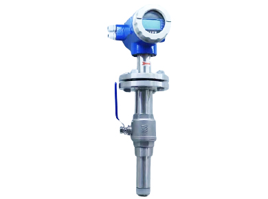
| Nominal Size Range | DN 15 – DN 600, flange or wafer style. | Economical from DN 100 upward; can be used on lines up to DN 2000 + . |
| Installation | Requires cutting the pipe or a shutdown for replacement; sensor, transmitter, and display are housed together—minimal wiring. | Hot‑tap installation allows insertion through a pressurized line—no shutdown needed; probe can be removed for service, transmitter can be mounted remotely. |
| Accuracy / Repeatability | ±0.5 % of rate. | Typically around ±1.0 %, depending on insertion depth and flow profile. |
| Pressure Loss | Theoretical zero head loss when the pipe is full. | Likewise, essentially zero head loss |
| Typical Applications | New pipelines, instrument rooms, small‑ to medium‑size lines where higher accuracy is required. | Retrofit of existing large lines, cooling‑water loops, municipal water mains, temporary or mobile metering points. |
Table of one-piece vs. inserts
Selection recommendations:
DN < 100: one-piece type preferred for high accuracy and short installation dimensions.
DN ≥ 100: and no downtime for retrofitting: Insertion type saves pipe cutting and flange material, shorter payback period.

Magnetic Flow Meter Mechanical Installation Procedure
Installation of magnetic flowmeter, can be completed in the following order: after stopping the transmission of clean pipes and flanges, check the caliber, lining, gaskets and bolts; spreader will be coaxial flowmeter in place, the flange inserted on both sides of the positioning, according to the diagonal plum blossom way to tighten the torque wrenches to the specified value in two times; in the table on both sides of the body of the additional support or expansion joints, to avoid the self-weight and thermal expansion stress; slowly open the upstream valve to fill the liquid and exhaust the bubbles to ensure full pipe; finally check the flange without seepage, grounding fastness, protective cover in place to confirm that the flow direction arrow is correct, can be transferred to the electrical wiring and zero commissioning. Ensure that the pipe is full; finally check the flange without leakage, grounding, protection cover in place, to confirm the flow direction of the correct arrow, you can turn to electrical wiring and zero debugging.
Electrical Wiring and Shielding
Electrical wiring, should use the manufacturer’s matching shielded twisted-pair cable to connect the excitation coil and signal electrode, and power cables laid in separate grooves, to maintain a distance of at least 150 mm, to avoid magnetic field coupling; signal line shielding layer in principle, only in the converter end of a single point of ground, to prevent the formation of the loop current noise, and the shielding of the excitation line is followed by the body of the protection of the ground is uniformly connected. Split installation should strictly comply with the “maximum cable length and distribution capacitance” limit, usually no more than 100 m, the distance should be used in excess of the relay amplifier. If located in a hazardous area in zone 0/1, the power supply and signals must be routed through intrinsically safe isolators or safety barriers, and special blue intrinsically safe cables must be used. The resistance between all grounding terminals and the protective earth busbar on site should be less than 4 Ω. After completing the wiring, reconfirm the excitation polarity, 4-20 mA load resistance and communication address before power-on commissioning.
Conclusion
Correct installation of magnetic flowmeter = choose the right location + good grounding + ensure full pipe + strict straight pipe section. With these four steps, you will get ±0.2-0.5 % long term accuracy, energy savings with almost zero pressure loss, and low maintenance life cycle costs.
Apure provides one-stop service for water, chemical, food, energy and other industries, from selection and calculation, to on-site survey, customized calibration and lifecycle maintenance, based on its complete product line of electromagnetic, ultrasonic flow meters, vortex flow meters, as well as its ISO 9001 quality system and Ex certification. If you’re planning a new project or want to upgrade your existing network with a more reliable, easy-to-integrate flowmeter, contact Apure engineering team for a professional solution that will help you protect your processes and add precision to your data.