
In every fluid-handling system—from municipal water networks to chemical reactors and steam distribution headers—flow rate is the foundational variable that links design intent to operational reality. Understanding which definition of flow rate matters for your application is not a semantic exercise—it drives pump sizing, heat‑exchanger loading, dosing accuracy, energy balances, custody transfer billing, safety interlocks, and regulatory reporting. In the sections that follow, we’ll look at flow rate in process control, the factors that influence it, how it’s measured, key flow‑rate types, and how Bernoulli’s principle underpins many industrial flow technologies.
What Is Flow Rate?
Flow rate is the amount of fluid that passes through a defined cross‑section (such as a pipe, channel, or instrument throat) per unit time. It answers the question: “How much fluid is moving, and how fast is it moving past here?” Depending on what “amount” means in your application, flow rate is expressed in several ways:
Volumetric Flow Rate (Q)
The volume of fluid passing a section per unit time.
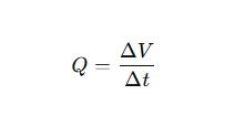
If the pipe is full and the average fluid velocity is vvv, then
Q=A×v
where AAA is the internal cross‑sectional area.
Typical units: m³/s, m³/h, L/min, gal/min.
Standard (or Normal) Volumetric Flow
Because gas volume changes with temperature and pressure, engineers often reference flow to agreed “standard” conditions (e.g., 0 °C & 1 atm, or another regional standard). Notation: Nm³/h, SCFM (standard cubic feet per minute). Converting to standard conditions allows apples‑to‑apples comparison and inventory control.
Flow Rate in Process Control
In process control, flow parameters directly determine the material balance, reaction rate, heat transfer efficiency and other key performance.
Closed-loop control: flow signal → PID controller → regulating valve/inverter pump to realize rationing or stable pressure and temperature.
Energy billing: steam, compressed air, natural gas and other required flow for internal or trade settlement.
Safety interlock: Abnormally high/low flow rate triggers pump jumping, valve shutdown or alarm to prevent dry running, air cooler freezing and uncontrolled reaction.
Factors Influencing Flow Rate
| Factor | Description | Typical Effect on Flow (Q) |
|---|---|---|
| Pressure Differential (ΔP) | Driving force from pump head, compressor discharge, or static elevation difference. | If system resistance is unchanged, ΔP ↑ → Q ↑. |
| Pipe Diameter (D) | Cross‑sectional area $A = \pi D^2 / 4$. Dictates velocity at a given volumetric rate. | D ↑ → Q capacity ↑. Pipes that are too small → high velocity & large pressure loss. |
| Fluid Viscosity (μ) | Internal friction opposing motion; strongly affects friction factor in laminar & transitional flow. | μ ↑ → friction ↑ → Q ↓ for a fixed ΔP. |
| Density (ρ) | Influences Reynolds number (Re) and fluid inertia; links volumetric to mass flow. | Change in ρ alters mass flow at a given volumetric rate; may shift flow regime. |
| Temperature & Phase State | Temperature swings change μ & ρ; flashing / vaporization can occur. | Thermal shock or phase change can disturb or choke flow, alter readings. |
| Valve / Filter Condition | Valve opening, throttling position, fouling, filter clogging. | Added resistance or plugging directly limits Q. |
| Pump / Compressor Performance | Equipment H–Q (head–flow) curve; wear, speed variation, impeller damage. | Curve shifts change available head → impacts achievable Q. |
Table of Factors Influencing Flow Rate
How to Measure Flow Rate?
Differential Pressure
Instrument type: Orifice plate, venturi, flow nozzle, wedge, V-cone, average Pitot tube, etc.
Principle: Throttle raises the flow rate → static pressure decreases. Bernoulli equation is given:

Where
C is the outflow coefficient,
A is the throttling cross-sectional area, and
β=d/D is the orifice ratio.
Advantages: mature standards (ISO 5167, etc.), high temperature and pressure resistance, can be used for trade measurement.
Disadvantages: permanent pressure loss (especially orifice plate), long straight pipe section, installation error affects accuracy, density compensation.
Recommended scenarios: high temperature and high pressure occasions; strict regulatory requirements; known fluid properties.
Electromagnetic Flow Meter
Principle: Electromagnetic flow meter based on Faraday’s law of electromagnetic induction. When a conductive liquid cuts through a magnetic field, an induced voltage is generated between electrodes:
Advantages: No moving parts; negligible pressure loss; handles dirty liquids, slurries, and fluids with suspended solids; very wide turndown.
Limitations: Requires minimum conductivity (typically ≥ 5 µS/cm); not suitable for oils, non‑conductive liquids, or gases.
Recommended Applications: Raw water, wastewater, pulp stock, mineral slurries, corrosive conductive chemicals; low‑maintenance service.

Ultrasonic Flow Meter
Measurement Modes:
Transit‑time: Sends ultrasonic pulses both upstream and downstream. The difference in travel time is used to calculate flow velocity. Best for clean liquids.
Doppler: Transmits sound and listens for the frequency shift caused by reflections from bubbles or suspended particles. Good for aerated or dirty fluids.
Form Factors: Clamp‑on (no pipe cutting), insertion probe, or full in‑line spool piece.
Advantages: Can often be installed without shutting down the process (especially clamp‑on types); negligible pressure drop; ideal for large pipe diameters and retrofit projects.
Limitations: Transit‑time accuracy falls off when excessive bubbles or solids are present. Doppler types need enough scattering material in the fluid to create a strong return signal. Proper acoustic coupling is essential. Straight pipe runs ahead of and after the meter improve accuracy.
Good Applications: Large existing pipelines, temporary or portable measurements, and open‑channel flow measurement when combined with a level sensor.

Vortex Flow meter
Principle: Vortex flow meter bluff body placed in the flow stream causes vortices to shed alternately downstream (a Karman vortex street). The frequency at which the vortices are formed is proportional to flow velocity. Electronics convert that frequency to flow.
Advantages: One technology that can measure liquids, gases, and steam; handles high‑temperature service (often above 400 degC / 752 degF); no moving parts.
Limitations: Requires sufficient flow velocity (and Reynolds number) to form stable vortices. Pipe vibration can create false signals. Turndown is moderate compared with magnetic or ultrasonic meters.
Good Applications: Plant steam, compressed air systems, general utility or process fluids when adequate straight‑run piping is available.

Turbine flow meter
Principle: Flowing fluid turns a multi‑bladed rotor suspended in the flow path. Rotor spin rate is proportional to volumetric flow. As each blade passes a magnetic or optical pickup, turbine flow meter produces a pulse. Pulses are counted and converted to flow using the meter’s K‑factor (pulses per unit volume).
Advantages: High accuracy and fast response. Works well on clean, low‑viscosity liquids and many gases.
Limitations: Moving parts wear over time; debris can foul or damage the rotor; calibration shifts when fluid viscosity changes. Usually requires upstream filtration.
Good Applications: Refined fuels, aviation fuel, light chemical solvents, calibrated natural gas service.

Positive Displacement (PD) Flowmeter
Types: Oval gear, rotary piston, nutating disk, helical or screw type, and others.
Principle: The meter mechanically captures and releases known, discrete volumes of liquid in repeating cycles. Counting the cycles gives a direct totalized volume.
Advantages: True volumetric measurement with very high accuracy (about plus or minus 0.1 to 0.2 percent is common in well‑maintained systems). Largely independent of flow profile. Widely accepted for custody transfer.
Limitations: Mechanical complexity; higher pressure drop than many other technologies; requires clean fluids (often lubricating) to protect internal parts.
Good Applications: Loading terminals, fuel dispensing, lube‑oil transfer, high‑value chemical products.
Coriolis Mass Flow meter
Principle: One or more measuring tubes are vibrated at a known frequency. When mass flows through the tubes, Coriolis forces cause a slight twisting or phase shift in the vibration pattern. The amount of shift is proportional to mass flow. The instrument also derives fluid density from the tube’s resonant characteristics and measures temperature.
Advantages: Direct mass flow and density in a single device; top‑tier accuracy (around plus or minus 0.1 percent class in many models); unaffected by flow profile or fluid phase changes within rated limits.
Limitations: Higher capital cost; relatively heavy; cost and size increase quickly with large pipe diameters; installation should minimize external vibration.
Good Applications: Fine chemicals, LNG transfer, recipe batching in food and beverage, pharmaceutical dosing, custody transfer of high‑value fluids.
Thermal Mass Flow Meter
Principle: A heated sensor element is cooled by moving gas. The electrical power required to maintain a constant temperature difference between the sensor and the gas is proportional to gas mass flow.
Advantages: Direct measurement of gas mass flow (no separate pressure or temperature compensation required in many applications); extremely wide turndown ratios (often 100 to 1 or more); insertion probes impose almost no pressure drop.
Limitations: Changes in gas composition affect calibration and accuracy; dust, oil mist, or other contaminants can foul the probe; high‑temperature service requires special construction.
Good Applications: Compressed‑air energy audits, plant nitrogen headers, flare and stack gas trending, general utility gas monitoring.
Open‑Channel Level‑to‑Flow Measurement
Measurement Setup: Use a primary hydraulic structure—such as a V‑notch weir, rectangular weir, or Parshall flume—together with a level sensor (ultrasonic, radar, or differential pressure). The measured liquid level (head) upstream of the structure is converted to flow using a calibrated head‑to‑discharge relationship.
Advantages: Suitable where the conduit is not full (partially filled pipe or open channel); well established for wastewater and environmental monitoring.
Limitations: Requires proper hydraulic approach conditions to be accurate; performance can degrade due to sediment buildup, trash, algae, or floating debris.
Good Applications: Wastewater treatment plant influent and effluent channels, stormwater and overflow monitoring, irrigation return flows.
Quick Selection Guide
- Conductive liquid? Try magnetic first.
- Non‑conductive and need no‑shutdown install? Consider clamp‑on ultrasonic.
- Hot steam or gas? Vortex or differential pressure.
- High‑accuracy liquid custody transfer? PD or Coriolis.
- Need direct mass plus density? Coriolis.
- Large gas line, minimal pressure drop? Thermal mass.
- Not a full pipe? Open‑channel element plus level sensor.
Conclusion
Flow rate is more than a number on a display; it is the control handle for material balance, product quality, energy efficiency, and system safety. Distinguishing between volumetric, mass, and standardized flow—and knowing when to apply each—prevents costly misinterpretation.
As you design, troubleshoot, or optimize a system, make flow rate the first variable you verify and the last one you take for granted. Accurate flow data turns complex plants into predictable processes—and that’s the foundation of safe, efficient, and profitable operations.
As a manufacturer specializing in process control and automation, Apure offers a complete line of flowmeters including measurement. All products are manufactured under a strict quality system (ISO 9001) and are available with explosion-proof ratings (Ex d / Ex ia) and a wide range of industrial communications (4-20 mA, Pulse, HART, Modbus, etc.) for the municipal water, chemical, food and pharmaceutical, metallurgical, mining, and energy industries. Apure’s engineering team also provides flow meter sizing calculations, on-site surveys, calibrations and long-term maintenance services to help you turn “theoretical flow” into “credible data”. For customized solutions, contact Apure.