
Electromagnetic flowmeter installation plays a critical role in ensuring accurate and stable flow measurement in water treatment, chemical processing, and industrial applications. While electromagnetic flowmeters are known for their high accuracy and low maintenance, improper installation can lead to signal noise, zero drift, and even complete measurement failure. Therefore, installation quality directly determines the long-term performance and reliability of the system.
Understanding Electromagnetic Flowmeter Installation Requirements
Before installation, it’s critical to understand how an electromagnetic flowmeter works: it measures flow based on Faraday’s Law of Electromagnetic Induction, meaning the pipe must be fully filled with conductive liquid.
Key Preconditions:
- Liquid must be conductive (typically >5 μS/cm)
- Pipe must remain completely full
- No large air bubbles or vacuum conditions


Installation Position Guidelines
Horizontal Pipelines (Most Recommended Configuration)
- Install the flowmeter on a fully filled horizontal pipe section
- Ensure the pipe is not at the highest point of the pipeline to avoid air accumulation
- Recommended position:
- Downstream of pump discharge
- Upstream of control valves (if possible)
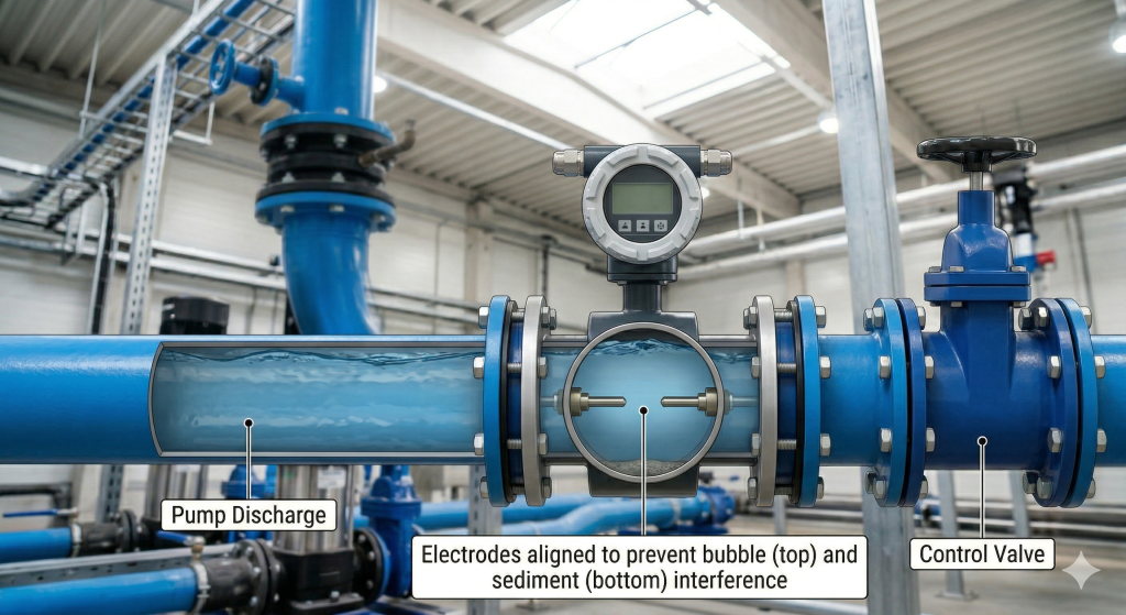
Engineering Tip:
Electrodes should be aligned at 3 o’clock and 9 o’clock positions to prevent:
- Air bubble interference (top)
- Sediment deposition (bottom)
Vertical Pipelines with Upward Flow
- Install only when the fluid flows from bottom to top
- This ensures:
- Pipe remains completely filled
- No risk of partial flow or empty pipe condition
- Minimum recommended flow velocity:
- ≥ 0.3 m/s (to prevent particle settling)
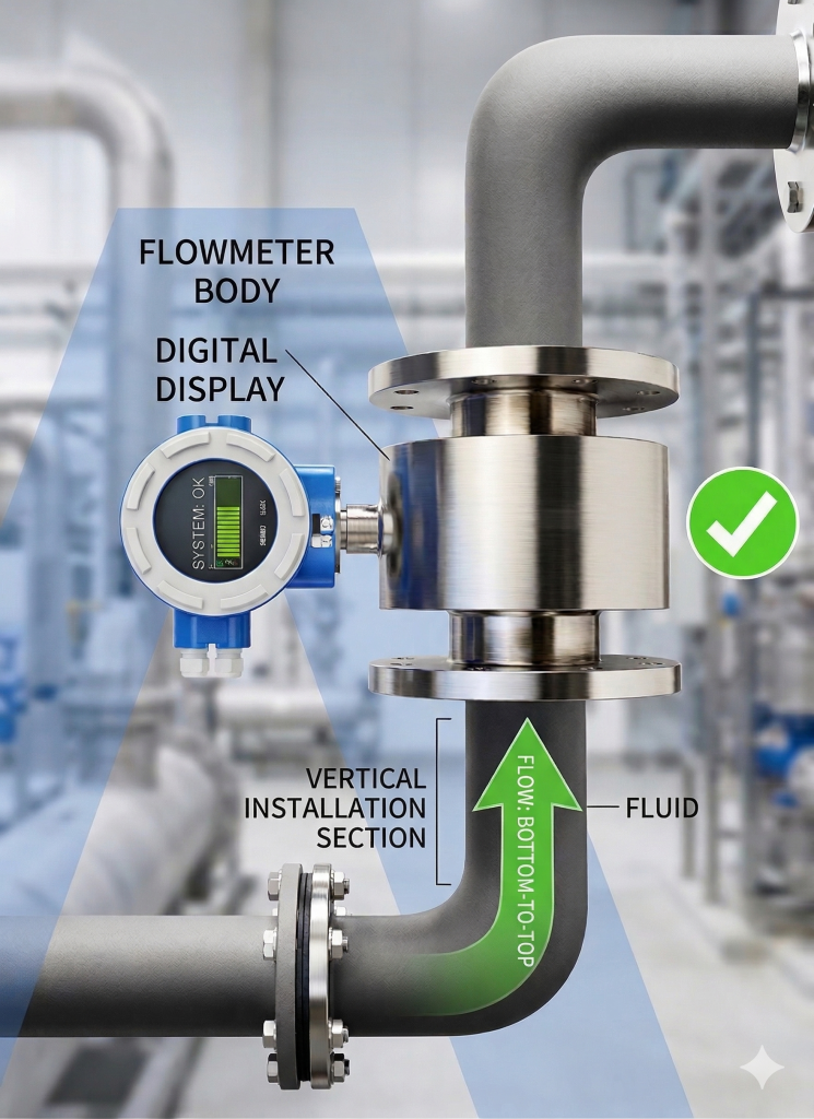
Avoid:
Downward flow installation → may cause empty pipe detection errors
Sections Where the Pipe Is Always Full
Choose locations where process conditions guarantee continuous full pipe, such as:
- After pumps (positive pressure zone)
- Low elevation sections of piping systems
- Before discharge into open tanks (but not at the outlet edge)
Do NOT install at:
- Pipeline high points → air pockets
- Gravity-fed partially filled pipes
- Free discharge outlets
Recommended Distance from Key Equipment
| Equipment Type | Recommended Position |
| Pump | ≥ 5D downstream (discharge side only) |
| Valve | ≥ 5–10D upstream |
| Elbow / Bend | ≥ 10D upstream |
| Reducer | ≥ 5D upstream |
Straight Pipe Requirements
To ensure stable flow profiles:
- Upstream: ≥ 10D (10 × pipe diameter)
- Downstream: ≥ 5D
Where disturbances exist (valves, elbows, pumps):
- Increase upstream length to 15D–20D
Electrode Orientation
Electrodes detect voltage generated by fluid movement, so positioning matters:
- Install electrodes at 3 o’clock and 9 o’clock
- Avoid top position (air bubbles)
- Avoid bottom position (sediment accumulation)
Grounding and Shielding
Proper grounding is non-negotiable for electromagnetic flowmeters.
Requirements:
- Use grounding rings if pipe is non-metallic (PVC, HDPE)
- Ensure single-point grounding
- Avoid interference from nearby electrical equipment
Common Issues Without Proper Grounding:
- Fluctuating readings
- Signal instability
- Measurement drift
Installation in Different Pipe Materials
| Pipe Material | Requirement |
| Metal Pipe | Natural grounding (usually sufficient) |
| Plastic Pipe | Must install grounding rings |
| Lined Pipe | Ensure electrode contact with fluid |
Avoiding Common Installation Mistakes
Frequent Errors:
- Installing at pipe high point → air accumulation
- No straight pipe section → unstable readings
- Incorrect grounding → signal noise
- Partially filled pipe → inaccurate measurement
Best Practices:
- Install after pump (discharge side)
- Use flow conditioning if needed
- Perform zero calibration after installation
Commissioning and Calibration
After installation:
- Check pipe is fully filled
- Verify grounding resistance
- Perform zero-point calibration
- Compare with reference flow (if available)
Application in Water Treatment Systems
Electromagnetic flowmeters are extensively used in:
- Wastewater treatment plants
- Chemical dosing systems
- Sludge flow monitoring
- Raw water intake measurement
Their non-intrusive design (no moving parts) makes them ideal for dirty or corrosive fluids.
Summary
Correct installation of an electromagnetic flowmeter is not just a mechanical task—it is a critical engineering step that directly affects measurement accuracy, system control, and operational efficiency. By following proper guidelines on positioning, grounding, and pipe conditions, users can maximize performance and minimize maintenance issues.
At Apure Flowmeter, we provide not only high-performance electromagnetic flowmeters, but also complete installation guidance and system integration support for water and wastewater applications.
From instrument selection to on-site commissioning, our team ensures your flow measurement system operates with maximum accuracy and reliability.
Contact us today to customize your flow measurement solution.