
What is an electromagnetic flowmeter?
An electromagnetic flowmeter (mag meters) is an instrument used to measure the flow rate of conductive liquids or slurries. Its operating principle is based on Faraday’s law of electromagnetic induction, which determines the flow velocity by measuring the induced voltage generated when the fluid flows through a magnetic field, and then calculates the flow rate. It has the advantages of no moving parts, low pressure loss, and the ability to measure various conductive media.
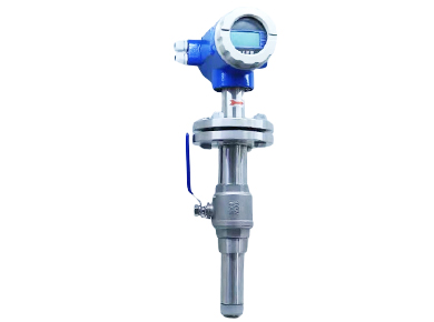


Detailed Explanation of the Working Principle of Electromagnetic Flowmeters


The core formula of the technical principle of electromagnetic flowmeters is based on Faraday’s law of electromagnetic induction:
E = B * v * L
Where:
- E: is the electromotive force (voltage) induced when conductive liquid flows through a magnetic field, usually measured in volts (V).
- B: is the magnetic induction intensity (magnetic flux density), which indicates the strength of the magnetic field, usually measured in teslas (T).
- v: is the velocity of the conductive liquid moving through the magnetic field, typically measured in meters per second (m/s).
- L: is the effective length of the conductive liquid cut by the magnetic field. In electromagnetic flowmeters, this typically refers to the distance between the inner diameter of the pipe or electrodes that is perpendicular to both the direction of the magnetic field and the direction of flow, with units typically in meters (m).
Connecting this basic formula to flow:
We are typically more concerned with volumetric flow rate (Q), which represents the volume of liquid flowing through the pipe per unit time, with units typically being cubic meters per second (m³/s) or liters per second (L/s). The relationship between volumetric flow rate and velocity is:
Q = v * A
Where:
- Q: is the volumetric flow rate.
- v: is the average velocity of the conductive liquid.
- A: is the cross-sectional area of the measuring pipe. For a circular pipe, A = π * (D/2)² = π * D² / 4, where D is the inner diameter of the pipe.
- Substituting the velocity v = Q / A into the formula of Faraday’s law of electromagnetic induction and considering the structural characteristics of the electromagnetic flowmeter, we can obtain a more direct formula relating the electromotive force and volumetric flow rate:
E ∝ B * Q / A * L
For a specific design of electromagnetic flowmeter, the magnetic flux density (B) and the geometric dimensions of the measuring pipe (including the cross-sectional area A and the effective length L, where L is typically related to the pipe diameter D) are fixed. Therefore, the induced electromotive force E is directly proportional to the volumetric flow rate Q:
E = k * B * Q
where k is a constant related to the flowmeter structure and magnetic field distribution.
More specifically, for a circular pipe with an inner diameter D and a uniformly distributed magnetic field, the induced electromotive force E can be expressed as:
E = B * D * v
Substituting v = Q / (πD²/4) into the above equation yields:
E = B * D * (Q / (πD²/4)) = (4 * B * Q) / (π * D)
Therefore, the volumetric flow rate Q can be expressed as:
Q = (π * D * E) / (4 * B)
Summary:
The core technical principle of electromagnetic flowmeters is Faraday’s law of electromagnetic induction. The induced electromotive force (voltage) is directly proportional to the magnetic flux density, fluid velocity, and effective length of the conductor. In practical applications, by measuring the induced electromotive force and combining it with known parameters such as magnetic flux density and pipe dimensions, the fluid’s volumetric flow rate can be precisely calculated.
Applications
- Water and wastewater treatment: Measurement of tap water, sewage, sludge, etc.
- Chemical industry: Measurement of various acidic, alkaline, and saline solutions, slurries, and other corrosive or solid-particle-containing media.
- Food and beverage industry: Measurement of sanitary-grade liquids such as milk, juice, and beer.
- Pharmaceutical industry: Measurement of high-purity liquids such as purified water and pharmaceutical solutions.
- Pulp and paper industry: Measurement of pulp flow and additive flow.
- Mining and Mineral Processing: Measuring slurry flow.
- Power Generation: Measuring cooling water, boiler feedwater, etc.
- Heating, Ventilation, and Air Conditioning (HVAC): Measuring water circulation system flow.
- Agriculture: Metering liquid fertilizers, pesticides, etc.
- Marine Industry: Measuring fuel oil, lubricating oil, cooling water flow, etc.
magnetic flow meter installation

- Before installation: Verify the model, inspect the appearance, read the manual, prepare tools, and understand the pipeline conditions.
- Location selection: Avoid strong electromagnetic interference and mechanical vibration, ensure easy maintenance, and leave sufficient straight pipe sections (5–10D upstream, 3–5D downstream).
- Pipeline requirements: Ensure the pipeline is filled with liquid, avoid empty pipes and bubbles, recommend vertical pipes flow from bottom to top, and clean new pipes first.
- Installation direction: Install according to the flow arrow markings. When installing horizontally, the electrode axis should be horizontal or vertical.
- Flange connection: Align the flanges, select appropriate gaskets, and tighten the bolts diagonally and evenly.
- Electrical wiring: Connect the power supply, signal, and ground wires strictly according to the wiring diagram, and properly handle the shielding wire.
- Reliable grounding: Use an independent grounding wire.
- Filling and degassing: Slowly fill with liquid and remove air from the pipeline.
- Parameter Settings: Set instrument parameters according to actual conditions, and calibrate as necessary.
- Other: Protect the instrument, monitor environmental temperature and humidity, and perform regular inspections.
Electromagnetic flowmeter calibration
Electromagnetic flowmeter calibration is designed to ensure measurement accuracy. The main steps include preparation, setting up the calibration system, taking measurements at different flow points, analyzing errors, adjusting instrument parameters as necessary, and generating a calibration report. Electromagnetic flowmeter calibration requires the use of conductive media and zero-point checks. Common calibration methods include the standard volume method, standard weight method, and standard flowmeter comparison method. It is recommended that calibration be performed every 1-2 years, which can be carried out by the manufacturer, a third-party institution, or a qualified user. It is essential to strictly follow the specific calibration procedures.
Advantages
- No moving parts: This is a significant advantage as it eliminates wear, reduces maintenance requirements, and makes the instrument less susceptible to blockage or damage from particulate matter in the fluid.
- Minimal pressure drop: The flow path within the flowmeter is unobstructed, resulting in minimal pressure loss, which is critical for the energy efficiency of pumping systems.
- Suitable for conductive liquids and slurries: Magnetic flow meters can accurately measure the flow of various conductive liquids, including water, wastewater, chemicals, and even slurries with some conductivity.
- High accuracy: Electromagnetic flow meters offer exceptional accuracy, typically within ±0.5% to ±1% of flow rate, making them suitable for critical applications.
- Wide range: They can accurately measure flow over a very wide range of flow rates.
- Bidirectional flow measurement: Many magnetic flow meters can measure flow in both forward and reverse directions, which is useful in certain processes.
- Sanitary design options: Magnetic meters feature smooth, seamless linings, making them an ideal choice for applications in the food, beverage, and pharmaceutical industries where hygiene is critical.
Limitations
- Requires conductive fluid: The primary limitation is that the measured fluid must have a minimum level of conductivity (typically around 5 µS/cm). They are not suitable for non-conductive fluids, such as pure hydrocarbons or deionized water.
- Bubble interference: The presence of large bubbles or non-conductive solids can disrupt the magnetic field, affecting measurement accuracy.
- Flow patterns affect accuracy: While generally less sensitive than other types, highly distorted flow patterns can affect accuracy. It is recommended to install sufficient straight pipe upstream and downstream of the meter.
- Initial cost may be higher: Compared to some simpler mechanical flow meters, magnetic flow meters may have a higher initial investment cost.
Magnetic flowmeter accuracy
- Factors affecting accuracy:
- Fluid conductivity:
- Electromagnetic flowmeters rely on the conductivity of the fluid. Insufficient conductivity can lead to inaccurate readings.
- Installation:
- Proper installation is critical. This includes:
- Sufficient straight pipe sections upstream and downstream of the flowmeter.
- Proper grounding.
- Avoiding cavitation in the pipe.
- Flow distribution:
- A well-developed flow distribution is critical for accurate measurement. Flow distribution distortion caused by bends or obstacles can introduce errors.
- Fluid uniformity:
- The fluid should be relatively uniform. Significant changes in temperature, density, or solid content can affect accuracy.
- Calibration:
- Regular calibration is necessary to maintain accuracy.
- Temperature and pressure:
- Extreme temperature and pressure changes can affect sensor performance.
- Instrument design and quality:
- The quality of the flowmeter’s components and its overall design play a significant role in its accuracy.
- Typical accuracy range:
- Typically, electromagnetic flowmeters can achieve an accuracy range of approximately 0.2% to 2% of flow.
- Under ideal conditions, some high-precision models can even achieve 0.1% accuracy.
- Key considerations:
- While electromagnetic flowmeters offer good accuracy for conductive liquids, specific application and operating conditions must be considered.
- When selecting an electromagnetic flowmeter, closely review the manufacturer’s specifications and ensure the flowmeter is suitable for the intended application.
What are the HS and HSN codes for magnetic flow meters?
HS code: 9026.1000
HSN code: 9026.1010